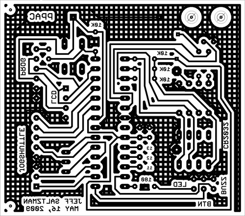
 Last night, I finished the board layout in EAGLE and got to work making it:
- Turned off layers in EAGLE except layer 1 and pads, and printed to a PDF,
- Rasterized PDF in Photoshop at 1200dpi and processed into a black+white image (right),
- Laser printed onto an L.L. Bean catalog page, with the print output set to "transparency,"
- Ironed onto 2.5" x 2.2" single-sided copper clad,
- Fixed gaps with etch-resist pen,
- Rubbed off paper and etched in ferric chloride for 15 minutes (though I'll use use the HCL and peroxide method in the future),
- Rubbed away ink with acetone,
- Tested trace continuity and scraped away tiny bridges with a knife,
- Drilled out all holes (1mm bit),
- Populated with parts and soldered it up,
- Pressed chips into sockets,
- Hooked up LCD, jog/shuttle, a button and LED.
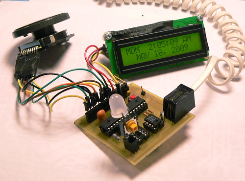
This is my first from-scratch Arduino-compatible board-- sure to be the first of many...:)
 Hifiduino
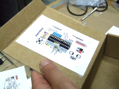 Paperduino
