Most importantly WM is coding Arduino! He already built a complete mode-switching, parameter-adjusting system with a figure diagram on-screen!
We'll make the suits themselves-- the displays with LED strips-- when we have a working circuit and software: we don't know where everything's going yet. So for a demo display I'm making a circuit board showing all 48 PCA9685 outputs on LED bars-- old school. Here's the one I'm scrapping-- got too much rework:
I've had a clean 1980 Atari VCS CX2600A for a dozen years or so, with joysticks, paddles, power brick, and cartridges, but the video output was always terrible, and I couldn't get any useful image out for a few years.
I followed (one of) Ben Heck's instructions on getting composite video out, but while everything checks out circuit-wise, and I get some video output, it was dirty and I couldn't stabilize it. Not a surprise since it wasn't working well to begin with!
Reading about the Flashback 2 from a few years ago, it turns out there's a way to add a cartridge port to it for playing old games. Instead of turning the Flashback into something even smaller, I wonder about going the other way: transplanting the Flashback 2 into the original 4-switch VCS, using as much original hardware as possible. It doesn't look like anybody has gone in this direction, but thankfully the VCS is well documented online; even the original service manual in PDF.
"Atari Hackback" seems like an appropriate project name. Thanks to Craigslist, it took a day to find a clean Flashback 2, and this handy reference shows where the cartridge pins go. There are a LOT of signals to reroute, but I'd like to preserve the hardware's connection to the PCB, so will need to find other solder points for attaching leads.
I have a tendency to over-order, whether at a restaurant or Fry's or Mouser or Adafruit, and I find myself with an excess of parts and other electronic junk. Some parts were destined for a project that took another turn, or I ordered parts to build two copies and only built one, or I raided a kit for a few parts and filed the rest away. I'm also a sucker for the free and cheap and just enjoy tearing down gear for motors, IC's, power parts and of course blinkable bits, always adding to the parts stores.
But some bins are filled to bursting, and I have more parts than I will use: time to pass this stuff along. Enter TGIMBOEJ: The Great Internet Migratory Box Of Electronics Junk: fill a box with stuff and send it to a stranger! The website hasn't had much action lately, but the request list is long, but I got in touch with somebody still interested. I'm hoping to send a box of tomorrow or Wednesday.
Note: new "NAR" tag added for "Not Arduino-Related" posts.
I've found more Arduino-compatible boards ('328- and '32u4-based) to add to the spreadsheet... there are always more! Plus I need to add the new official Arduinos, so:
I have mixed feelings about Arduino hardware. Their official boards have diversified in odd directions, and non-official versions keep doing everything better. For instance, it's strange that with so much going on on a Leonardo board, there's still no 3.3V/5V switch or jumper.
I tried using the laser to remove some spray paint, and... I declare it a dud. Two major factors stymied this process for me for the moment:
I didn't have the right spray paint (matte black) nor the right environment (dry and warm) for the paint I did have. What I did get to stick to the copper had a very uneven surface.
The laser is... finicky. I can't tell if the layers were wildly inconsistent, if the paint behaved differently as it dried, or if maybe the laser had trouble, not liking the cold temperature or moist environment. I never can tell if it's about to give up.
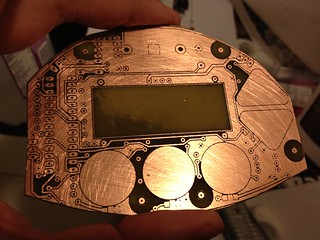
Impatient as usual, I used my regular method: laser printer toner transfer. Determined to make a 2-sided board work, I spent a while aligning corner crop marks and pre-taping the paper with the toner before laminating it to the copper. The toner transfer worked beautifully-- perfect result laminating it ten times (5 up, 5 down), but the top-bottom alignment, while close, may not be close enough. At this point it's etched (see photo) and drilled, but there are still bridges and the misalignment will make assembly an adventure.
Looking at guides online, (especially the tutorial at An Engineer's Life which so many people are linking to today,) it does seem like most people use a photographic process and abandon toner transfer when they go for double-sided and SMD. Before going that route, I want to take toner transfer further though-- I've had such good results so far, the only issue is top-bottom alignment. The biggest sources of alignment error:
Top-bottom alignment of printed out patterns. A light box, some magnets, and tape should do the trick-- I need to see the registration targets better. Update: lightbox on the way from B&H.
The laminator binds and jerks sometimes, which could distort the pattern slightly. It's hard to tell without sending through a test image, but it seems like time to take apart the laminator and see about modding it to separate the rollers a hair.
I'm happy with a slightly lower level of quality with toner transfer because it's a simpler process with fewer (and cheaper) expendables that can also transfer labeling to the top and bottom after etching.
I've had a great time working on circuit designs in Eagle the last week or so-- after my surgery, my sciatic pain is mostly gone and I'm able to concentrate again! Still, I'm mostly confined to the neighborhood and can't lift or bend or exert myself for another few weeks, so I'm happily plugging away at a few projects, the main one of which is my latest coffee grinder timer.
The timer PCB's odd shape was dictated by the enclosure's design, resulting in a 100mm x 74mm board. It needed to be double-sided, but traces were made wide and vias were kept to a minimum in the interest of home prototyping. I've had great success with toner transfer in the past, but not for 2-sided boards, and not for anything large.
A PCB-production process I've wondered about is using a laser engraver to remove an etch-resistant layer on copper before normal etching. The best and most successful example I've found is on Instructables: "Custom PCB Prototyping using a Laser Cutter," where the author uses flat black Krylon indoor/outdoor paint as the resist.
The example (at right) shows a single-sided board, but I'm primarily interested in using the process for excellent top-bottom registration. Before attempting the large board, I will first try some small pieces with test shapes, then I'll try a double-sided ATmega32u4 breakout board (my own design), then Grinder Timer 5. Stay tuned...
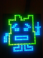
The Mooninite kits are the same except for the different bags of LED's, and while I soldered up Ingingot in no time (at right), Err's kit became a parts donor. In shuffling through some old parts, I just found its big bag of BIG 10mm pink LED's-- says 68 but I counted 74. So big! So PINK!!! They scream for a project of their own. Free association... LED's make flashy things... flashy things for Burning Man... boogie at Pink Mammoth.... er, do they need a sign?
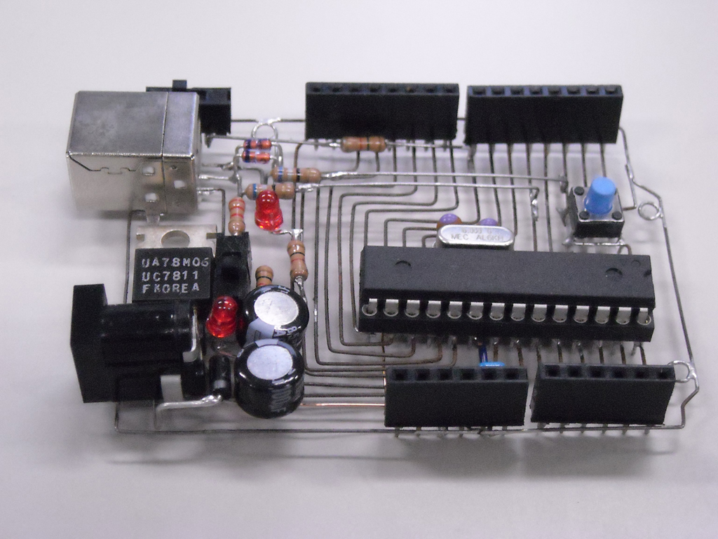
I love homemade boards, and this layout is by Carlos Rodrigues is lovely! From Flickr:
Construir o meu próprio Arduino, fase 3: alguns upgrades.
Tem agora melhor protecção contra ruídos na alimentação, reset automático ao iniciar um upload, protecção contra excesso de corrente no USB, e o bootloader do Arduino Uno.
Translated by Google:
Build my own Arduino, phase 3: a few upgrades.
You now have better protection against noise on power, automatic reset to start an upload, protection against excess current in USB bootloader and Arduino Uno.
Adafruit did a lovely job with the Arduino team on the new official Arduino Micro. Everything is tiny, with a smaller ATmega32u4 and parts on the top and bottom, some the smallest components available-- seriously micro! It's available now for $25.
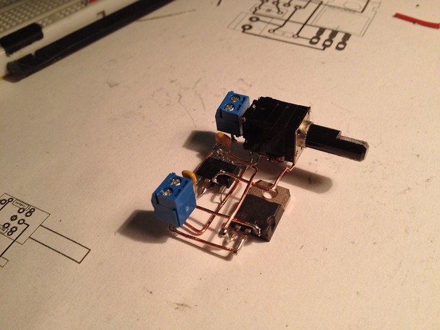
I built this 3D, freeform circuit as a test project. I've seen a few lately and love the way they look, and after making this circuit, I'm excited about this method as an alternative to point-to-point soldering or etching for small, one-off boards.
It's a dimmer circuit: a 555-timer-based PWM generator driving a high power MOSFET. I kept it simple and focused on a method, not on making anything particularly fancy.
Here's a video walk-through of the circuit:
I edited a schematic for a board I'd built earlier, adding a scrounged 10k audio potentiometer with switch. The parts list was short:
10k potentiometer with switch,
2 2-pin screw terminals (input and output),
NE555 8-pin chip,
fat npn MOSFET,
2 1N4148 diodes,
2 capacitors: .1uF and 1uF,
330 ohm resistor
The first step was the Eagle board layout. With air-wires I moved things around for a while to get things close, and routed and rerouted a few times before setting some guidelines:
Put the major components where you want them first.
Pack the rest of the components in paying attention to keeping traces short.
Small 2-lead components can fit later, with one lead overlapping its signal, the other reached by a branch made from its lead.
Lay out a few long traces that hit the most pins and cover the most ground first. Try to get those traces in a straight line or aligned in an L- or S- or U- arrangement, more or less.
Avoid branching, unless the branch can be a component's lead.
Small kinks and zig-zags are OK and may be built with straighter wire segments later, with pins bent to get where they need to be.
Don't think much about top/bottom layering and about crossing lines. There will be room to cross a wire here or there. Try not to cross, but you can worry about top and bottom later.
Then on to building, which breezed by. Pre-bent wires made it a straightforward, by-numbers sort of thing, and I used the components' leads instead where I could, reducing the number of parts. Building notes:
Print out a sheet to see the circuit different ways, to use as a pattern. Run the same sheet through the printer, taking advantage of the print options:
Aligned top center, scale 2 or 3 (what will fit), with all layers drawn.
Aligned lower left, scale 1, with all layers,
Aligned lower right, scale 1, just the traces.
Note: also print scale 1 mirrored versions too, of all layers and traces only, to see things from the bottom, which is how things are soldered.
In the trace-only print-out, number the longest traces to make wires for them.
Small kinks in the pattern don't generally need to be bent-- wires and pins will bend during soldering.
Clip leads after soldering, unless it has to butt up as a T. It's easy to clip after soldering, and wires can shift during soldering.
I kept it simple and methodical so I could scale it up to bigger circuits. I have to say that the result surprised me in how quickly and easily the board came together.
I'm looking forward to using this on a few other cicruits, maybe a PIC-based USB-serial converter, or a multichannel MOSFET-based switcher or SSR or... good stuff from this :) Then there's the question of how to mount this, or cast it in some material.
Rupert Hirst's amazing resin-encased headphone amplifier is a work of art and shows a novel (to me) way of building a circuit without any mounting board. His buildlog shares many great details, especially about the casting process.
Kimio Kosaka files his incredible "Arduino Skeleton" board under "O'baka Project" which he says: "means a stupid project. This project is to make things which is not art and which is not usable. Now, I am making Arduino skeleton by using steel wires." Hmm, they look like usable art to me! Maybe a mis-translation. He lists instructions:
How to make.
Design single side PCB by EAGLE-CAD. (Base circuit is Metaboard)
Print out this PCB pattern.
Trace this PCB pattern by steel wire. (0.46mm in diameter)
Soldering
I used a flux of the strong acidity for the steel wire soldering.
These inspired me to make one of my own, which turned out to be a faster, easier, cleaner way to make a simple 1-off circuit than home etching or point-to-point soldering, if the process is refined.
Arduino is part of my life and has been for years now: I constantly use the homemade, Arduino-based appliances in my home the same way I use appliances other people made. But while I'm hooked on building out my world the way I like it, sometimes a project only needs a handful of pins, so I just ordered a few ATtiny85 and 2313's to try my hand at [gulp] proper AVR programming. It's too bad that Arduino is going toward the high end with the Due instead of toward the low end with smaller, simpler circuits and chips, but I'm happy to go elsewhere to learn. I could hot-wire the Arduino environment to program an ATtiny, but I'd like to try transitioning to a more fully-featured IDE for future development anyway, so programming an ATtiny will be a good sub-project.
Speaking of "the high end," the $25?! (OK really $50 but still!) Raspberry Pi has been on my radar, maybe for something using some cameras and image analysis-- things an Arduino would struggle with. I'm especially excited lately after hacking around with a $25 WiFi access point and OpenWrt... wow! Amazing how much power can be had for so cheap, and how many how-to's can help you along.
What do you think? Have you left the "safe" space that Arduino provides, and moved to different processors and IDE's? please leave a comment.
Jay Silver's "MaKey MaKey: An Invention Kit for Everyone" raised over a half million Kickstarter dollars (above a $25K goal) and he deserve the crazy success-- the video is a brilliant demo/sales piece that on its own inspires you to make things... and of course buy a Makey Makey. Just awesome stuff, and at its core: an Arduino! I'm adding it to the spreadsheet... after ordering one or two...:)
I've tried Fritzing a few times and get pretty far along quickly, only to get my nets tangled up-- not connected where I thought they were. Then I manage to crash it while I try to figure it out. This time, I'm going to try a tutorial and actually stick to it, and see how far I get!
We have two pantries in our flat, one of which could use some light.
There's an outlet in there, but a simple solution won't do: I have more circuitry and time on my hands than I can handle, and the least I can do is make an over-complicated pantry light.
Parts lying around to use:
AC-DC converter blocks with screw-terminals outputting 12V at 2A. I have a bunch of these-- came with the LED strips.
A length of white LED strip.
Lots of TIP-120-style MOSFETs, intended for a second light suit. It's fun to have a lot of high power switches around.
Spare Arduino-compatible board "StripDuino" by "Tinkeract.com," now defunct it seems. Thanks for sending the free board!
The idea is simple-- rest your hand on the large strip on the door sill as you scan the pantry contents. The light will turn on if you tap the strip, or it will fade if you leave your hand on it.
This design solves the problem uniquely with:
Very large switch surface,
Variable brightness by holding the switch,
Indirect lighting from compact, dense LED strip tucked out of view.
I have a hardware sketch working in terms of the key elements of the controlling Arduino system:
Capacitive touch sensing works between pins D5 and D6 with a 1M resistor
Touch surface works: aluminum foil with soldered wire plus a layer of hot glue and tape.
PWM works with the MOSFET to control the LED strip nicely, with the board's 3.3V logic.
For the light strip at full power, I measure 240.8 mA at 11.85 V, so 2.85 W of power. This is not much but it scales proportionally to the length of the strip.
To do:
Capture the working circuit in an Eagle schematic.
Build a looping sketch with the tap/hold fading behavior.
It has been a while since the design was announced, but Arduino Leonardo boards are actually making their way to vendors-- you can get one now! (Er, if you can find one, they seem to have sold out of Adafruit and SparkFun...)
The big change with this board is the switch from the ATmega328 to the ATmega32u4, which includes built-in USB, so no more FTDI chip or secondary ATmega to handle USB. Other substantial changes that will affect compatibility:
SPI not connected to digital pins
I2C pins now D2 and D3
more analog inputs
separate USB serial
I feel bad for shield-makers needing to rework things for this layout, but such is progress I suppose.
With 32U4-based boards being available and officially supported in the new IDE, I'll [sigh] add just added them and a few clones to the spreadsheetover the next few days:
Since building my Flight Suit last year, I haven't posted many photos or videos of the finished suit or of its inner workings, so I will make a series of posts about it over the next few weeks. I would not have been able to complete the project without the generous sharing of the OSHW community, and I hope some bit of my project's details will be of some use to somebody.
All work on the suit revolved around a composite image I put together early to lay out the LED light strips, with each level numbered (0-11) and each segment getting a unique letter designation (A-X). Arms are shown up and down since the suit adapts to the arms' positions, lighting up each segment according to its current level.
From that composite image, I built a segment spreadsheet to keep track of the 22 LED strips through construction and programming. It includes all of the segments' lengths and progress steps, plus designations of levels, segment letters, and channels.
The system's electronic components are distributed throughout the suit (image at right; click to go to Flickr for more notes) using existing fittings on the suit when possible:
The 12V Li-ion battery pack which powers the suit fits nicely in the right thigh pocket. Its switch acts as the main system on/off switch. Spare battery packs fit in zippered ankle pockets.
The main system board sits in the upper left arm pocket: an Arduino-compatible board with a shield containing the left arm accelerometer board and jacks for the right arm accelerometer, MOSFET boards, ZX-Sound, and remote control.
The right arm accelerometer sits in a small pocket sewed onto the right upper arm.
MOSFET boards hang in the chest pockets, attached to the leads routed through the suit to the LED strips.
The ZX-Sound audio board is mounted with Velcro to the included patch on the left chest.
The remote control dangles from its cat 5 cable or attaches to an existing Velcro strip at the waist.
I plan to post at least once on each of these topics:
System layout, schematics and final firmware
LED strips: planning, splitting/making, mounting
MOSFET boards: driving the LED strips
ZX-Sound: incorporating audio response into the system
Arm accelerometers: reading and filtering and controlling segment/level mapping
Remote control
Main program design: fast looping, modes, ShiftPWM
Wearability: marrying the system and the suit, sewing, gluing, maintenance
If there's something else you're curious about, please email me or post a comment. As I post more, I will continue to upload photos to my Flickr set.