 I prefer breadboard-friendly Arduino-compatible boards like Boarduino and iDuino, but I keep wanting functionality people have built into shields like Adafruit's Motor Shield and Batsocks' TellyMate Shield.
All I want in an Arduino:
- ATmega328
- FTDI programming header
- Arduino "form factor" with odd D7/D8 spacing and standoff holes
Necessary items:
- microcontroller: ATmega328, socket, capacitor
- clock: oscillator and 2 caps, or a resonator
- reset: 90-degree (side) button, 10K resistor
- FTDI cable interface: 6-pin header, capacitor
- Power: Barrel connector, 2-pin header
- icsp (2x3)
- i2c (4)
spi (6)(nah)
- Power indicator: LED, 1K resistor
- TX/RX indicators: 2 more LEDs, 2 more 1K resistors
- Power regulation: 7805, 2 capacitors, jumper
- Diode to prevent inverted power hookup
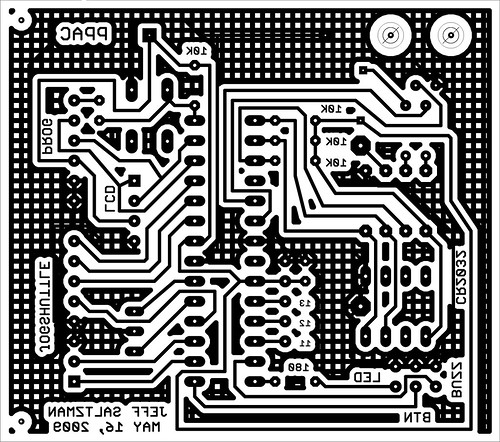
Update 12/29: I got a single-sided board laid out with just four jumpers, and I'll tear it up and redo it with the programming header where I want it, jumping TX and RX across the board. The files for the "Severino" single-sided board helped me figure out the routing.

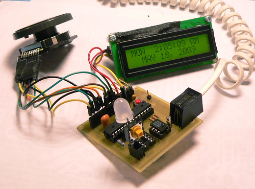
 Clocky
 Alarm Clock/Bedpost "-MAWD-"
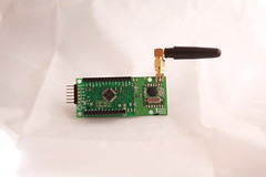


 Hifiduino
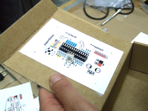 Paperduino

 I got my old test sketches working again for the


