Wednesday, March 31, 2010

New(ish) "Official" Arduinos

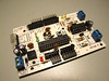
The Arduino FIO, announced at the New York Uno Punto Zero meeting, is Shigeru Kobayashi's Funnel I/O board, now officially in the Arduino stable, manufactured and sold by SparkFun Electronics ($25). It runs at 3.3V, at 8MHz, and includes voltage regulation, a LiPo charging chip, and an XBee socket. Note that the USB connector is only for power, not for programming.

The Arduino Nano 3.0 by Gravitech ($35) got a lot of press in the last week after being stocked in the Make: Magazine Maker Shed (though it was actually rolled out in July). This revision has LEDs for power, RX, TX, and D13; auto power sensing; power regulation and USB programming interface-- pretty much everything a full-sized Arduino has, plus the two extra analog input pins available on the smd ATmega328.

Both are listed on my comprehensive Arduino-compatible boards spreadsheet. I find it interesting that neither of these conforms to the original Arduino form factor, which makes sense given how little space smd components occupy and how often auxiliary circuits are built on solderless breadboards. Still, breadboard tinkerers miss out on the awesome functionality built into shields, which was the motivation behind the Minimalduino board.

Monday, March 29, 2010

Minimalduino: Three, Please!

I got the latest version (.89) of my Minimalduino board to Laen at DorkbotPDX before the deadline this morning-- looking forward to getting three copies of it!

I met all of the specs I laid out in my original post, except there are no TX/RX LEDs and no SPI header. Keeping it exactly the same size as the Diecimila/Duemilanove meant more (and longer) jumpers than I wanted, but I like the layout over all, and the jumpers won't matter for the DorkbotPDX order since those will be 2-sided boards.

My favorite features are the button type options (top or side), power connection options (barrel or screw terminals, plus .1" separated pins), I2C header, and extra standoff mount-- the three Diecimila/Duemilanove standoff mounts never seemed adequate to me.

Friday, March 19, 2010

Motoruino

Guilherme Martins announced his fantastic "Motoruino" (flickr set) freeduino board on March 9. It has a shield-compatible pin layout, power pins for each Arduino pin, and a L293D motor driver circuit on the right side. I like that he didn't bind the driver to any particular Arduino pins and included three ways to attach motors' leads. I can't wait to get my hands on one.

Tuesday, March 16, 2010

PPAC Fixes, Minimalduino, Timer

I've been busy lately and haven't had as much time as I'd like to tinker, but I've gotten things moving in the last two weeks and am overdue to post.

Hoping to show off the alarm clock a little, I brought the PPAC (including power block, valve tree, and tank) to the Make:SF Meetup last month, and while talking and hooking it up at the same time, plugged the AC supply into the DC power socket! The voltage regulator fizzled but the power board seems fine otherwise. Strangely, of all things, the LCD display was dead as well... though I may have killed it when disassembling the can..:o I ordered a better looking LCD replacement which I'll install in the next few days-- green-on-black instead of black-on-green: Newhaven NHD-0216K1Z-NSPG-FBW-L.

The minimalduino project is still moving forward: I'm using a test board I made at home a few weeks ago, populated with as little as possible: chip, caps, resonator, female headers, reset and male FTDI header. I'll move a few traces around but it's pretty much there, and hope to get three test boards made through the DorkbotPDX PCB order, deadline noon on March 29. I've built a spreadsheet with costs, and it seems like I could make a batch of 25 kits at just under $15 each. I'm not sure if it's worth the trouble though.

A few weeks ago, I built a new coffee grinder timer with a re-worked sketch and single board, then handed it off to fellow coffee fiend HF for ideas on how to make the ideal grinder timer. One thing we agreed on is that tenths of a second would be cool, so last night I had a great time working out a sketch to drive a common anode 3-digit 7-segment display using an SAA1064 IC. Of course having a sketch to start with made things straightforward-- thanks Alessandro Saporetti! I reworked the code to make it more general purpose, using all of the chip's functions including multiplexed (versus not) and changing the constant current output (7 output levels possible, from 3 to 21mA). [Video to come]