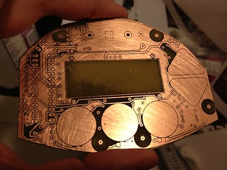
- I didn't have the right spray paint (matte black) nor the right environment (dry and warm) for the paint I did have. What I did get to stick to the copper had a very uneven surface.
- The laser is... finicky. I can't tell if the layers were wildly inconsistent, if the paint behaved differently as it dried, or if maybe the laser had trouble, not liking the cold temperature or moist environment. I never can tell if it's about to give up.
Looking at guides online, (especially the tutorial at An Engineer's Life which so many people are linking to today,) it does seem like most people use a photographic process and abandon toner transfer when they go for double-sided and SMD. Before going that route, I want to take toner transfer further though-- I've had such good results so far, the only issue is top-bottom alignment. The biggest sources of alignment error:
- Top-bottom alignment of printed out patterns. A light box, some magnets, and tape should do the trick-- I need to see the registration targets better. Update: lightbox on the way from B&H.
- The laminator binds and jerks sometimes, which could distort the pattern slightly. It's hard to tell without sending through a test image, but it seems like time to take apart the laminator and see about modding it to separate the rollers a hair.

some idea for alignment:
ReplyDeleteattach 1st (top) layer and drill 2 holes into pcb before etching, then
attach 2nd layer (bottom) and use the 2 holes (and 2 pins) for aligning ...
roland
Yes that would help a lot, thank you! I'm trying everything now, hooked on getting tight top-bottom alignment. Since this post I got a light box which helps to align corner registration marks of the top and bottom copper layer prints-- much better result for a little breakout board.
DeleteDid you end up populating the board; where is the final result? I'm not a huge fan of toner transfer as I've had mostly Brother brand printers which are not suitable for that purpose. Also, the fact that you risk smudging the PCB while ironing it makes it extremely frustrating. I am planning on making a few Arduino boards in the near future though
ReplyDeleteI populated some of the board-- the Arduino core part-- and it didn't work. Too many problems in too many places, I decided to bail on the design.
ReplyDeleteI haven't had the troubles you describe with toner transfer using a laminator to transfer from the paper to the copper.