Showing posts with label EAGLE. Show all posts

Monday, December 17, 2012

Laser for PCB Prototyping?

I've had a great time working on circuit designs in Eagle the last week or so-- after my surgery, my sciatic pain is mostly gone and I'm able to concentrate again! Still, I'm mostly confined to the neighborhood and can't lift or bend or exert myself for another few weeks, so I'm happily plugging away at a few projects, the main one of which is my latest coffee grinder timer.

The timer PCB's odd shape was dictated by the enclosure's design, resulting in a 100mm x 74mm board. It needed to be double-sided, but traces were made wide and vias were kept to a minimum in the interest of home prototyping. I've had great success with toner transfer in the past, but not for 2-sided boards, and not for anything large.

A PCB-production process I've wondered about is using a laser engraver to remove an etch-resistant layer on copper before normal etching. The best and most successful example I've found is on Instructables: "Custom PCB Prototyping using a Laser Cutter," where the author uses flat black Krylon indoor/outdoor paint as the resist.

The example (at right) shows a single-sided board, but I'm primarily interested in using the process for excellent top-bottom registration. Before attempting the large board, I will first try some small pieces with test shapes, then I'll try a double-sided ATmega32u4 breakout board (my own design), then Grinder Timer 5. Stay tuned...

Thursday, November 1, 2012

555-Based Dimmer 3D Circuit

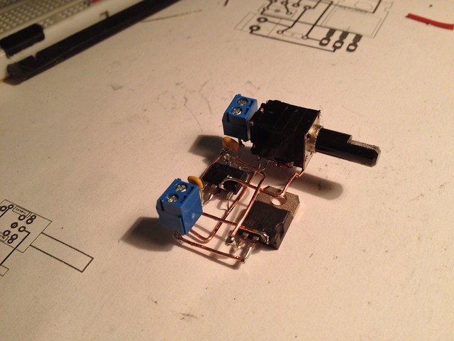
I built this 3D, freeform circuit as a test project. I've seen a few lately and love the way they look, and after making this circuit, I'm excited about this method as an alternative to point-to-point soldering or etching for small, one-off boards.

It's a dimmer circuit: a 555-timer-based PWM generator driving a high power MOSFET.  I kept it simple and focused on a method, not on making anything particularly fancy.

Here's a video walk-through of the circuit:

I edited a schematic for a board I'd built earlier, adding a scrounged 10k audio potentiometer with switch.  The parts list was short:
  • 10k potentiometer with switch,
  • 2 2-pin screw terminals (input and output),
  • NE555 8-pin chip,
  • fat npn MOSFET,
  • 2 1N4148 diodes,
  • 2 capacitors: .1uF and 1uF,
  • 330 ohm resistor
The first step was the Eagle board layout.  With air-wires I moved things around for a while to get things close, and routed and rerouted a few times before setting some guidelines:
  • Put the major components where you want them first.
  • Pack the rest of the components in paying attention to keeping traces short.
  • Small 2-lead components can fit later, with one lead overlapping its signal, the other reached by a branch made from its lead.
  • Lay out a few long traces that hit the most pins and cover the most ground first.  Try to get those traces in a straight line or aligned in an L- or S- or U- arrangement, more or less.
  • Avoid branching, unless the branch can be a component's lead.
  • Small kinks and zig-zags are OK and may be built with straighter wire segments later, with pins bent to get where they need to be. 
  • Don't think much about top/bottom layering and about crossing lines.  There will be room to cross a wire here or there.  Try not to cross, but you can worry about top and bottom later.
Then on to building, which breezed by.  Pre-bent wires made it a straightforward, by-numbers sort of thing, and I used the components' leads instead where I could,  reducing the number of parts.  Building notes:
  • Print out a sheet to see the circuit different ways, to use as a pattern.  Run the same sheet through the printer, taking advantage of the print options:
    • Aligned top center, scale 2 or 3 (what will fit), with all layers drawn.
    • Aligned lower left, scale 1, with all layers,
    • Aligned lower right, scale 1, just the traces.
    • Note: also print scale 1 mirrored versions too, of all layers and traces only, to see things from the bottom, which is how things are soldered.
  • In the trace-only print-out, number the longest traces to make wires for them.
  • Strip a length of stripped solid-core wire for each long trace.  Bend them to shape with pliers, clipping to length, using the trace-only print as the pattern.
    • Small kinks in the pattern don't generally need to be bent-- wires and pins will bend during soldering.
  • Clip leads after soldering, unless it has to butt up as a T.  It's easy to clip after soldering, and wires can shift during soldering.
I kept it simple and methodical so I could scale it up to bigger circuits.  I have to say that the result surprised me in how quickly and easily the board came together.

I'm looking forward to using this on a few other cicruits, maybe a PIC-based USB-serial converter, or a multichannel MOSFET-based switcher or SSR or... good stuff from this :) Then there's the question of how to mount this, or cast it in some material.

Wednesday, January 4, 2012

MRF24WB0MA Breakout

I soldered this up last night, using an EAGLE CAD board layout to guide me. The headers are set up and labeled and I'm ready to use the example from i/o blog-- more tonight!

Monday, May 9, 2011

Minimalduino v.105: Curvy Trace Fun

I've been trying out some Hope RFM12B radio modules-- very cool and inexpensive!-- which run off 3.3V. I've been using MinimalDuinos since they're 5V/3.3V switchable, and I got three version .97 boards made last year, with curvy traces, and they're coming in handy.

I have a few boards I'll need to get made over the next few months, so to warm back up with EAGLE, I polished up a straight (normal) trace version .105 board and set to curving it up. It took about an hour and a half, going around trace by trace in move mode, lots of command-clicking and dragging in the middle of trace segments to adjust their arcs. I submitted it to the DorkbotPDX PCB order before the deadline hit, and I can't wait to see what I get :) Design files and snapshots can be found here.

A key goal of the design is to have a good single-sided pattern for home etching, so I'll also make one by hand after fattening up as many traces as possible.

V.105 with straight traces:

Compare to V.105C, with curvy traces:

Friday, May 14, 2010

Rounded EAGLE Routing?

Trying to spread traces around, I wondered how the rounded wire bend routing options worked in CadSoft EAGLE. There's a free-form, spline sort of wire bend option, and I went around to all the traces on the latest minimalduino version (which needs a better name btw), widening and pushing and pulling traces to try to fill empty areas. Sort of looks hand-drawn, kind of hippyish. I was hoping to find a way to eliminate one of the jumper wires, but no luck. I introduced an air-wire, actually, but can fix that with a little nudging.

Not sure whether to get a few of the rounded or "normal" versions when the DorkbotPDX PCB order is due. I got the idea trying to arrange the traces in the lower left and upper middle areas, after working in some patterning in the diagonals. Your opinions are most welcome!

Update 5/21/10: The mail to Laen at DorkbotPDX never sent?! Went to mail him asking him if they worked out, and the mail was in "Drafts". Stayed up late Sunday night tweaking them and... crap! Guess I'll have to wait for the next order; had a 3-digit 7-segment display board too, based on an SAA1064..:(

Sunday, January 3, 2010

Minimal*duino

I reworked the one-layer board to got everything routed nicely in two layers, and etched it last night with the layers very well aligned! Now to get flux-- without it, the vias need their own little lead, which is quite a pain. I'll build it out today and test it, then look at board house prices for making a minimal order, seeing how many I'd have to order to get the price down to $10/kit (with no extras). I wonder about rebuilding it in KiCad though-- I've about had it with EAGLE's inefficient UI.

Monday, May 18, 2009

Alarm Clock Board Built!

Last night, I finished the board layout in EAGLE and got to work making it:
  • Turned off layers in EAGLE except layer 1 and pads, and printed to a PDF,
  • Rasterized PDF in Photoshop at 1200dpi and processed into a black+white image (right),
  • Laser printed onto an L.L. Bean catalog page, with the print output set to "transparency,"
  • Ironed onto 2.5" x 2.2" single-sided copper clad,
  • Fixed gaps with etch-resist pen,
  • Rubbed off paper and etched in ferric chloride for 15 minutes (though I'll use use the HCL and peroxide method in the future),
  • Rubbed away ink with acetone,
  • Tested trace continuity and scraped away tiny bridges with a knife,
  • Drilled out all holes (1mm bit),
  • Populated with parts and soldered it up,
  • Pressed chips into sockets,
  • Hooked up LCD, jog/shuttle, a button and LED.
It behaved exactly like it did on the breadboard! Now I can focus on the right button/LED combo and casing, redoing the relay board, and tightening up the program.

This is my first from-scratch Arduino-compatible board-- sure to be the first of many...:)

Wednesday, May 13, 2009

PPAC Board V7.3: Hand Routed

Work on the main board (alarmduino?) is progressing nicely, but not without a false start-- after etching and building out the first board last week, I found that the 5-pin header to mate with the Futurlec DS1307 mini board was backwards! But the DS1307 doesn't need much circuitry, and the mini board had a lot of unused space, so I decided to revise the alarm clock main board with the clock built-in.

The latest PPAC layout has the DS1307 on the right side, with the battery holder on the bottom and interrupt going to A3; I would have tested the schematic on a breadboard tonight but I can't find any 10K resistors. I added an I2C EEPROM too (or, at least a socket for one-- I don't have the little sucker yet) for program settings, maybe a log of wake up times, and relief for the ATmega's built-in EEPROM.

Not to whine, but I'm getting impatient with EAGLE's autorouting for 1-layer boards-- I can usually find a route for the missed connections, and it's annoying to have to push around so many traces to fit them in. This board layout was routed completely by hand after EAGLE kept leaving at least four air wires. It might work as-is, or I may spread into the unused areas and widen the traces. Must resist the temptation to just etch it and build it before breadboarding the whole thing-- I want to have the program ready for this specific circuit, since I shuffled some pins around on the EAGLE layout after converting it from my previous working breadboard circuit.

Wednesday, April 8, 2009

Prioritizing Projects

Too many parts and projects lying around-- need to nail down an order and finish something soon!

PPAC should be the first priority-- I've gotten it to work, but attempts at packaging it have been held up by the fact that I'm still not sure about UI and whether I even want to use high pressure air or a pump. Would be great for a contest, but not unless it's (1) done and (2) demonstrated through video. First-things-first time:

  • EAGLE: set up with display, jog/shuttle, RTC, buttons, switch, power, and output. Don't worry about whether output is to relays or oo's,
  • Arduino: get a good program working on the breadboarded circuit,
  • Figure out best fill/empty plan,
  • THEN start laying it out in 3D for the final build.

Next up (while figuring out ppac fill/empty plan) is a working growduino with relays, no sensing, no logging, and no solar-- don't try everything at once! Better to get something growing.

The invervalometer is so close, but needs:

  • To be reeled back to the breadboard after the stuffing problem-- Arduino OK?!
  • Panasonic-capable trigger,
  • Serious power system consideration.

The mutetater should be a simple build:

  • Limit to Sony since that's easy to read, and I have Samid's old Sony TV,
  • Breadboard > potato should be simple using a dorkboard with female header pins.