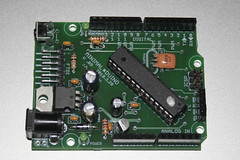
 Three copies of my latest Minimalduino design (V .89) arrived today, fabricated in the DorkbotPDX circuit board order. I built one with all components and it works perfectly, with the exception of the 3.3V regulator having a different pinout than the 75LXX part I used in Eagle-- oops...
A SparkFun protoshield and Adafruit motor shield fit on top fine, but with very little (read: "zero") clearance over the tall capacitors I used-- they'll get some tape on top, and the next revision will use shorter caps or orient them sideways. Excited to work with my first factory-made board, I shot and posted some build pictures with a few notes.
To correct in the next revision:
- Fix 3.3V regulator (MCP1700-330) pinout,
- Lay out for wider/shorter or horizontal voltage regulator caps for better shield vertical clearance.
- 5V/3.3V switchable with a jumper on three pins (though it will limit power),
- Top pad and through holes under 7805 for better heat dissipation,
- Credits (CC, author names) on bottom silk screen,
- Optional resettable fuse?
- Optional on/off switch or jumper pins?
- Try to reduce the number and length of jumpers.

I have been working on a home etchable board like this, but with school it has been put on the backburner. I think the i2c and the FTDI interfaces are brilliant. I would have never thought of that. I really like the 90 degree buttons, barrel or terminal power, and especially the option for crystals or oscillators. If you are planning on selling the boards on your site, I would like to buy a couple of bare pcbs. If you plan on releasing your eagle files, I would love to be able to make my own boards.
ReplyDeleteThanks spuder! I plan to make up a batch once I nail down a "final" design with caps lying down, a 5V/3.3V jumper, and a few other little things.
ReplyDeleteThe files are available through the first link in this post which takes you here.
I am looking at the schematic, and I don't see a positive lead hooked up to the usb. I wonder if I have an older file or something
ReplyDeleteOk, it is a button, not a usb. My bad.
ReplyDeleteHi,
ReplyDeleteI just found your design while looking for the protoduino. I like your minimal design, but it looks strikingly like the "Diavolino" from EvilMadScientist.
What are the differences/advantages to your design over the diavolino?
-Andrew
Thanks, I was working on this before Diavolino, yeah they're pretty similar! But Minimalduino:
ReplyDelete* puts things you need at the edges of the board-- reset button and LED's-- so a simple shield won't block them.
* is mostly 1-sided, so it can be homemade.
* has (overkill) 5V regulation option and an extra 3.3V regulator.
* can be 5V or 3.3V, or switchable (newer revisions).
* has a fourth standoff mount hole, before the Uno introduced a new (offset why?!) fourth hole standard.
* has options everywhere: power connector (barrel, screw terminals, pins, solder direct, USB socket soon), regulation, top or side button, resonator or crystal+caps.
* has a socket for the chip.